Description
Sliding Door Actuator / Mechanism
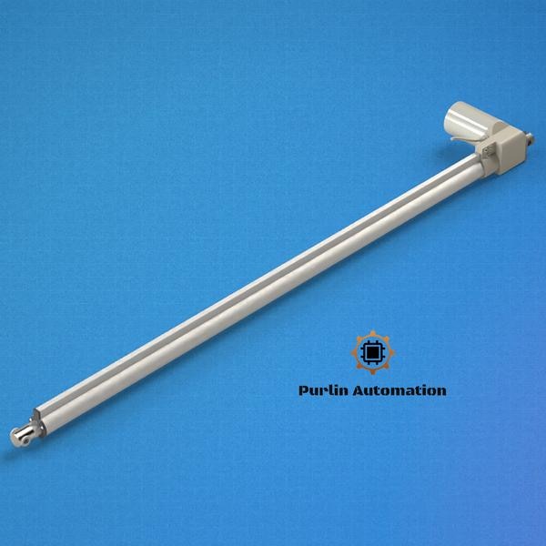
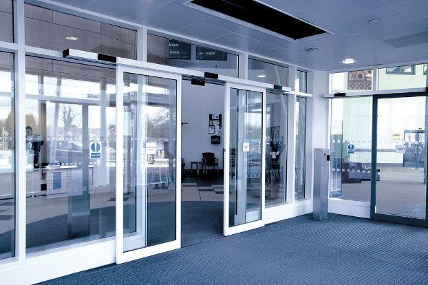
A Sliding Door Actuator / Mechanism is an electromechanical system used to automatically open and close sliding doors or gates. It converts the rotary motion of a motor into linear movement that drives the door along a track. These systems are widely used in industrial, commercial, and residential applications for convenient and controlled door operation.
Main Components
Electric Motor – Provides the driving power.
Linear Actuator / Drive Mechanism – Converts rotary motion into linear motion.
Guide Rail / Track – Allows the door to slide smoothly.
Control Unit – Controls opening and closing functions.
Limit Switches / Sensors – Stops the door at the correct position.
Mounting Brackets & Couplings – Connect actuator with the door structure.
Working Principle
When power is supplied, the motor rotates.
The actuator mechanism (lead screw, belt drive, or rack and pinion) converts this rotation into linear motion.
The linear motion pushes or pulls the sliding door along the rail.
Limit switches stop the actuator once the door reaches the fully open or closed position.
Key Features
Smooth and quiet operation
High load carrying capacity
Compact and robust design
Low maintenance system
Adjustable opening speed
Weather-resistant construction
Typical Technical Specifications
Stroke Length: 200 mm – 1500 mm
Load Capacity: 500 N – 5000 N
Voltage: 12V / 24V / 230V
Speed: 10 mm/s – 60 mm/s
Protection Class: IP54 / IP65
Applications
Automatic building entrance doors
Industrial warehouse sliding doors
Hospital automatic doors
Clean room doors
Residential sliding gates
Advantages
Hands-free automatic operation
Improved safety with sensors
Energy efficient
Suitable for automation integration (PLC / remote control)
Specifications
| speed |
variable |
| input power |
24 vdc |
| load |
1000 n |